Breaker Masking: The Hidden Fire Risk That Plug-In Solar Laws Are Designed to Prevent
By PlugInSolarUS Editorial · Published 2026-05-24 · Updated May 2026 · 10 min read
Breaker masking is the primary fire safety concern for plug-in solar systems. Learn how solar current can hide overloads from your circuit breaker, the two-tier US approach (≤391W vs. 392W–1,200W), and why it’s a solved problem.
Safety Note
For systems above 391W, UL 3700 certification requires breaker masking protection — typically a dedicated GFCI circuit, Power Control System, or oversized conductors. Systems ≤391W are safe on shared circuits due to their low current output. If you’re installing a system above 391W and are unsure whether your outlet is on a dedicated circuit, consult a licensed electrician before installing.
What Is Breaker Masking?
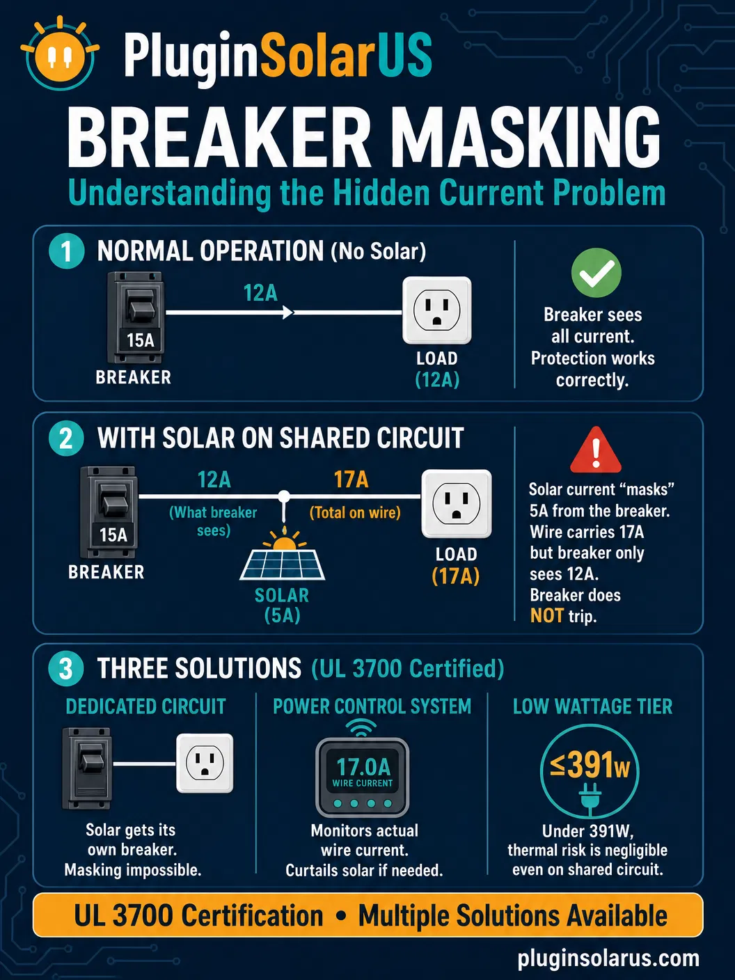
Breaker masking is a phenomenon where a plug-in solar device feeding power into a circuit effectively “cancels out” some of the load current as seen by the circuit breaker. The result: the breaker detects less current than is actually flowing through the wires, potentially allowing dangerous overloads to persist without tripping the breaker.
Circuit breakers are the last line of defense against electrical fires. They are designed to disconnect a circuit when current exceeds the wire’s safe carrying capacity. When breaker masking occurs, this safety mechanism is compromised — the breaker is effectively “blinded” to the true current flowing through the wires it’s supposed to protect.
This is the single most important fire safety concern specific to plug-in solar systems. For systems above 391W, it is the primary reason why UL 3700 certification requires breaker masking protection (most commonly through a dedicated circuit). For systems ≤391W, the risk is negligible and no dedicated circuit is needed.
How Breaker Masking Works
To understand breaker masking, you need to understand how circuit breakers measure current and how plug-in solar changes that measurement.
Normal Operation (No Solar)
In a standard home circuit without solar, current flows in one direction: from the electrical panel, through the circuit breaker, along the wires, and to whatever appliances are plugged in. The circuit breaker sits at the beginning of this path and measures ALL current flowing to the loads. If you plug in a hair dryer (14A) and a space heater (14A) on the same 20A circuit, the breaker sees the full 28A and trips immediately, preventing the 14-gauge wire from overheating.
With Plug-In Solar on a Shared Circuit (The Problem)
When a plug-in solar system is connected to the same circuit as other appliances, it introduces a second source of current. The solar system feeds current into the circuit at a point downstream of the breaker. This solar current flows directly to nearby loads without passing through the breaker.
From the breaker’s perspective, it only measures the net current flowing from the panel: the total load current minus the solar current being supplied locally. The breaker has no way to know that additional current is flowing through the wires beyond its measurement point.
The Math: A Concrete Example
Consider a typical worst-case scenario documented in research from Lawrence Berkeley National Laboratory:
| Component | Current | What’s Happening |
|---|---|---|
| Hair dryer | 14A draw | Pulling current from the circuit |
| Space heater | 14A draw | Pulling current from the circuit |
| Plug-in solar system | 10A feed-in | Supplying current INTO the circuit |
| Wire carries | 28A | 14A + 14A = 28A through the wire (DANGEROUS) |
| Breaker sees | 18A | 28A - 10A = 18A (below 20A trip threshold) |
In this scenario, 28 amps flows through wire rated for a maximum of 20 amps. The wire rapidly overheats. But the breaker only detects 18A — safely below its 20A trip threshold — so it does nothing. The wire continues to overheat until insulation degrades, potentially causing an electrical fire.
How Much Overload Is Actually Dangerous?
Not all overloads are immediately catastrophic. Research from the Fraunhofer Institute and German electrical safety organizations has established risk thresholds:
| Overload Level | Effect on Wire | Fire Risk |
|---|---|---|
| 0–10% over rating | Minimal additional heating | Negligible — within safety margins |
| 10–20% over rating | Slightly faster insulation degradation | Low — may reduce wire lifespan but unlikely to cause fire |
| 20–40% over rating | Significant heating, insulation softening | Moderate — sustained overload could cause fire in hours |
| 40%+ over rating | Rapid overheating, insulation melting | High — fire possible within minutes |
In our example above, 28A on a 20A-rated wire represents a 40% overload — firmly in the “high risk” category. This is why breaker masking on shared circuits is treated as a serious safety concern, not a theoretical edge case.
The European Perspective
Europe has addressed breaker masking differently because their electrical systems have different characteristics. European homes use 230V/16A circuits with 2.5mm² wire, which has more thermal margin than US 120V/15A circuits with 14-gauge (1.6mm²) wire. The Fraunhofer Institute determined that a 600W limit on European circuits creates a maximum possible overload of 2.6A (about 16%) — within the “low risk” category. Germany later raised this to 800W, accepting a 3.5A (22%) worst-case overload as still acceptable.
Applying the same 3.5A safety buffer to US 120V circuits would allow only 420W of plug-in solar per household on a shared circuit. This insight directly influenced the US approach: rather than choosing a single solution, US states adopted a two-tier framework that recognizes low-wattage systems are inherently safe on shared circuits while requiring additional protection for higher-wattage systems.
The US Two-Tier Approach
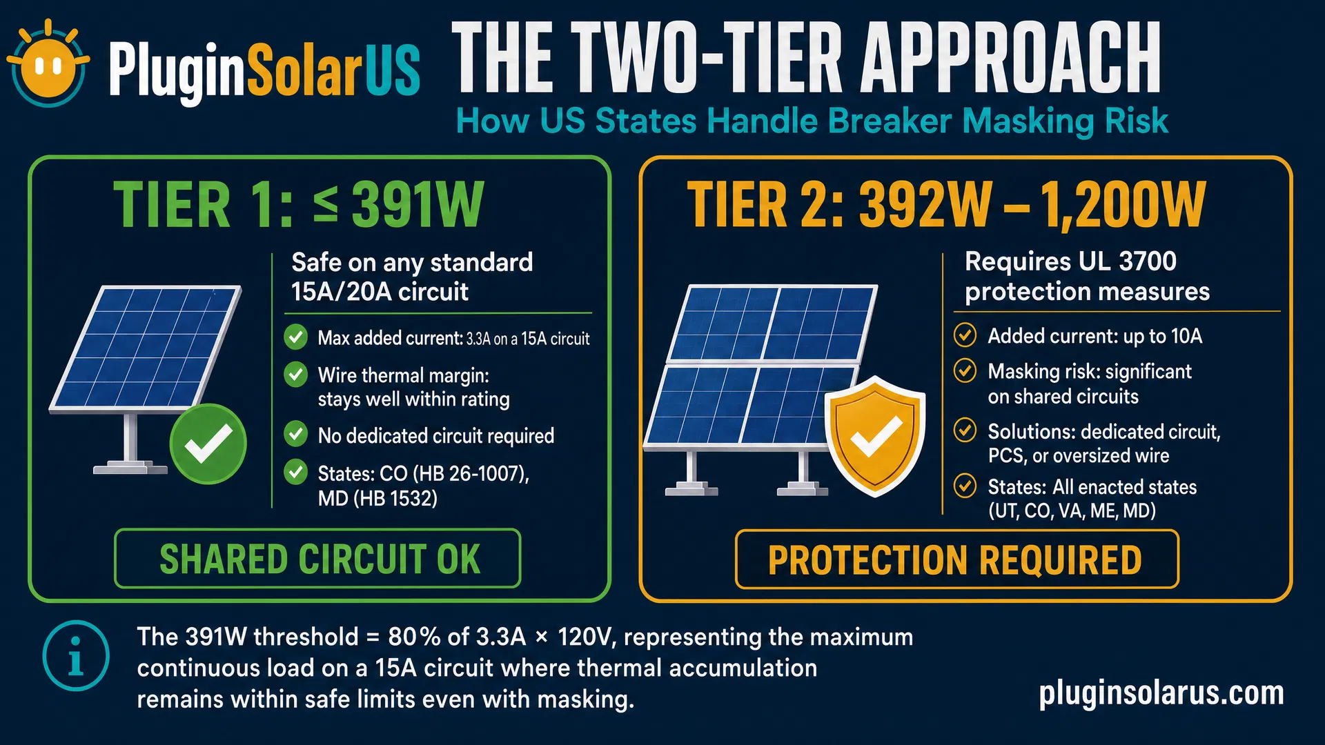
Several US states have adopted a nuanced two-tier system that distinguishes between low-wattage systems (where breaker masking risk is negligible) and higher-wattage systems (where additional protection is required):
Tier 1: Low Wattage (≤391W) — Safe on Shared Circuits
At 391 watts or below on a 120V circuit, the maximum solar current is only 3.26A. Even in a worst-case scenario where the circuit is already at its continuous load limit (12A on a 15A breaker), the total wire current would be 15.26A — still within the wire's safety margin (NEC requires 14-gauge wire to handle at least 125% of the breaker rating, giving an 18.75A thermal capacity).
States recognizing this tier:
- Colorado (HB 26-1007): Systems ≤391W are exempt from UL listing requirements and building code alterations. DIY self-install is explicitly allowed.
- Maryland (HB 1532): Devices with power output of 391 watts or less are exempt from the UL certification (listing) provisions.
- Maine (LD 1730): Systems ≤420W require no utility notification and allow self-installation without professional oversight.
At this wattage level, a dedicated circuit is not required because the physics of breaker masking cannot create a dangerous overload condition.
Tier 2: Higher Wattage (392W–1,200W) — Requires UL 3700 Certification
For systems above 391W, the breaker masking risk becomes meaningful and must be addressed. However, a dedicated circuit is not the only solution. UL 3700 certification provides multiple engineering pathways to eliminate the risk:
- Dedicated GFCI circuit (most common): Solar system gets its own breaker. No other loads share the wire. Masking is physically impossible.
- Power Control System (PCS): A smart breaker or monitoring device that measures actual wire current (not just net current at the panel). If total current approaches the wire rating, the system curtails solar output. Craftstrom Solar already offers a NEC-certified smart breaker using this approach.
- Oversized conductors: Using wire with a higher ampacity rating (e.g., 10-gauge wire on a 20A circuit) so that even with masking, the wire never exceeds its thermal limit.
The key point: UL 3700 certification ensures breaker masking is addressed, but it does not mandate a single specific solution. The market is free to innovate, and the certification process validates that whatever approach is used achieves the required safety outcome.
The NEC 705.12(B) “120% Rule”
The National Electrical Code has long addressed a similar concern for traditional rooftop solar through NEC 705.12(B), known as the “120% rule.” This rule limits the sum of the main breaker rating plus any solar backfeed breaker to 120% of the panel’s busbar rating. In other words, the worst-case overload on the panel’s internal wiring is capped at 20%.
Plug-in solar on a shared circuit does not benefit from this rule because the solar current enters the circuit downstream of the branch circuit breaker, not at the panel. The 120% rule protects the panel’s busbar; it does nothing to protect individual branch circuit wires from masking.
This distinction is crucial: breaker masking is a branch circuit problem, not a panel problem. The solution must be applied at the branch circuit level — which is exactly what a dedicated circuit provides.
Why Dedicated Circuits Eliminate Breaker Masking
A dedicated circuit is one that serves only a single device or system — in this case, only the plug-in solar system. When no other loads share the circuit:
- The only current flowing through the wire is the solar system’s output
- The breaker sees 100% of the current flowing through the wire (there’s nothing to “mask”)
- The wire can never carry more current than the solar system produces
- A 1,200W system on a 120V circuit produces a maximum of 10A — well below the 20A breaker rating
For systems above 391W, a dedicated circuit remains the most common and straightforward solution to breaker masking. It eliminates the problem by design rather than trying to detect or mitigate it after the fact. However, as noted above, it is not the only certified pathway — Power Control Systems and oversized conductors can achieve the same safety outcome.
Additional Safety Measures in US Laws
US plug-in solar legislation includes multiple layers of protection against overcurrent hazards:
| Safety Measure | How It Helps | Required By |
|---|---|---|
| Dedicated circuit or equivalent | Eliminates breaker masking entirely (for systems >391W) | UL 3700 certification (multiple pathways accepted) |
| GFCI protection | Detects ground faults and shock hazards; provides additional overcurrent awareness | All enacted state laws |
| 1,200W system cap | Limits maximum current to 10A on 120V (50% of 20A breaker rating) | All enacted state laws |
| UL certification | Ensures inverter has current-limiting protection and cannot exceed rated output | All enacted state laws (UL 1741, UL 3700) |
| 20A minimum circuit | Ensures wire gauge (12 AWG) has thermal margin above maximum solar output | Utah HB 340, Colorado HB 26-1007 |
Together, these measures create a system where the maximum possible current through any wire (10A from a 1,200W system) is only 50% of the breaker’s trip threshold (20A) and well within the wire’s safe carrying capacity. There is no scenario under normal operation where breaker masking can occur.
Smart Solutions Already Emerging
Technology-based solutions are already entering the market that allow safe operation on shared circuits without requiring a dedicated circuit:
- Power Control Systems (PCS): Craftstrom Solar already offers a NEC-certified smart breaker that monitors actual wire current and curtails solar output if the circuit approaches its limit. This is an approved pathway under UL 3700.
- Smart outlets: Outlets with built-in current sensors that disconnect the solar system if total circuit current exceeds a safe threshold, detecting masking events in real time.
- Current-sensing inverters: Inverters with CT (current transformer) clamps that monitor total circuit current at the breaker, not just their own output. If the combined current exceeds the breaker rating, the inverter reduces output automatically.
These solutions are gaining certification and market availability. For systems ≤391W, they are not even necessary — the physics already ensures safety on shared circuits. For larger systems (392W–1,200W), UL 3700 certification validates whichever approach the manufacturer chooses.
Practical Guidance for Homeowners and Renters
How to verify you have a dedicated circuit
- Check your breaker panel: Look for a breaker labeled for the specific outlet you plan to use. If it’s labeled “Bedroom” or “Living Room” (implying multiple outlets), it’s likely a shared circuit.
- The appliance test: Plug a lamp into the outlet, then turn off the breaker. Walk through your home — if ANY other outlet or light also lost power, it’s a shared circuit.
- Hire an electrician: For certainty, a licensed electrician can trace the circuit and confirm whether it’s dedicated. They can also install a new dedicated circuit if needed (typically $200–$500).
What if you’re a renter?
Renters have multiple options depending on system size and state law:
- Use a ≤391W system: In states like Colorado and Maryland, systems at or below 391W can safely plug into any existing outlet on a shared circuit. No dedicated circuit needed, no landlord permission needed for the electrical connection itself.
- Request a dedicated circuit: Some state laws (like Maine’s LD 1730) include provisions requiring landlords to provide or allow installation of a dedicated circuit for plug-in solar upon tenant request. Your landlord may be required to accommodate this at their expense.
- Use a Power Control System: As PCS-equipped systems become more widely available, renters will be able to safely use higher-wattage systems on shared circuits without any electrical modifications.
Check our State Tracker for your state’s specific provisions regarding renter rights and dedicated circuit requirements.
The Bottom Line
Breaker masking is a real and well-understood fire safety concern for plug-in solar systems. It is not a theoretical risk — it is a predictable consequence of physics when solar current feeds into a shared circuit. However, it is also a completely solved problem through multiple engineering approaches.
The US two-tier framework provides a practical path forward:
- Systems ≤391W: Safe on shared circuits. No dedicated circuit needed. The math shows the overload risk is negligible. Colorado and Maryland explicitly exempt these systems from UL listing requirements.
- Systems 392W–1,200W: Require UL 3700 certification, which ensures breaker masking is addressed through dedicated circuits, Power Control Systems, or oversized conductors.
If you’re considering a larger plug-in solar system (above 391W), a dedicated circuit ($200–$500 to install) remains the most common and straightforward solution. On a dedicated circuit, breaker masking is physically impossible. Combined with GFCI protection, UL-certified equipment, and the 1,200W system cap, the safety margins are substantial.
For smaller systems (≤391W), you can safely plug into an existing shared circuit — the physics ensures your wiring stays within safe limits even in worst-case scenarios.
Sources
- Gerber et al.: Barriers to Balcony Solar and Plug-In DERs in the United States, Energies 18(8), 2132 (April 2025) — Lawrence Berkeley National Laboratory
- WIRED: Why Balcony Solar Panels Haven’t Taken Off in the US (May 2025)
- Balcony Solar Safety Factsheet — Technical safety analysis of plug-in DER systems
- Mike Holt’s Forum: Plug-in Solar and GFIs — Professional electrician discussion on breaker masking (December 2025)
- Greentech Renewables: What is the Panelboard Sizing 120% Rule?